Pstat vs Vent Area
PstatStatic vent activation pressure · barg
⚙ Customize chart axes
X-axis · Pstat
Y-axis · Vent area (m²)
Axes control display only. A custom X range also recalculates the curve within valid input bounds.
Complying with NFPA 68 and EN 14491 Standards
Sign in to manage your private plant list.
Automatically populated from the selected standard dust preset.
Used in fireball diameter formula: D = K · (V / n)¹/³. Defines external hazard envelope.
Dust analysis is highly sensitive to the input data and assumptions, so it is the user's responsibility to verify the results before official use
L: Effective enclosure length associated with the maximum flame travel distance. Its determination depends on enclosure geometry and vent arrangement.
D: Effective hydraulic diameter of the enclosure cross-section perpendicular to the flame travel direction—not the explosion vent diameter.
barg; default 0 barg. Used in NFPA 68 L/D correction when L/D > 2. Ensure 1 + Pinitial > 0.
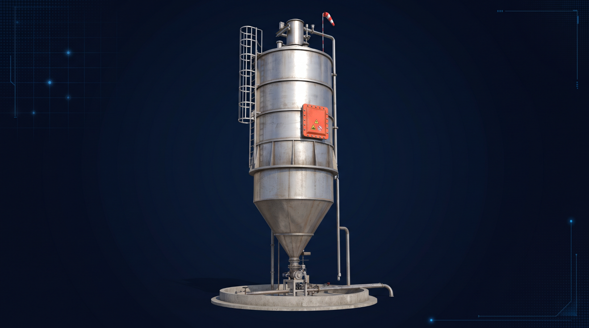
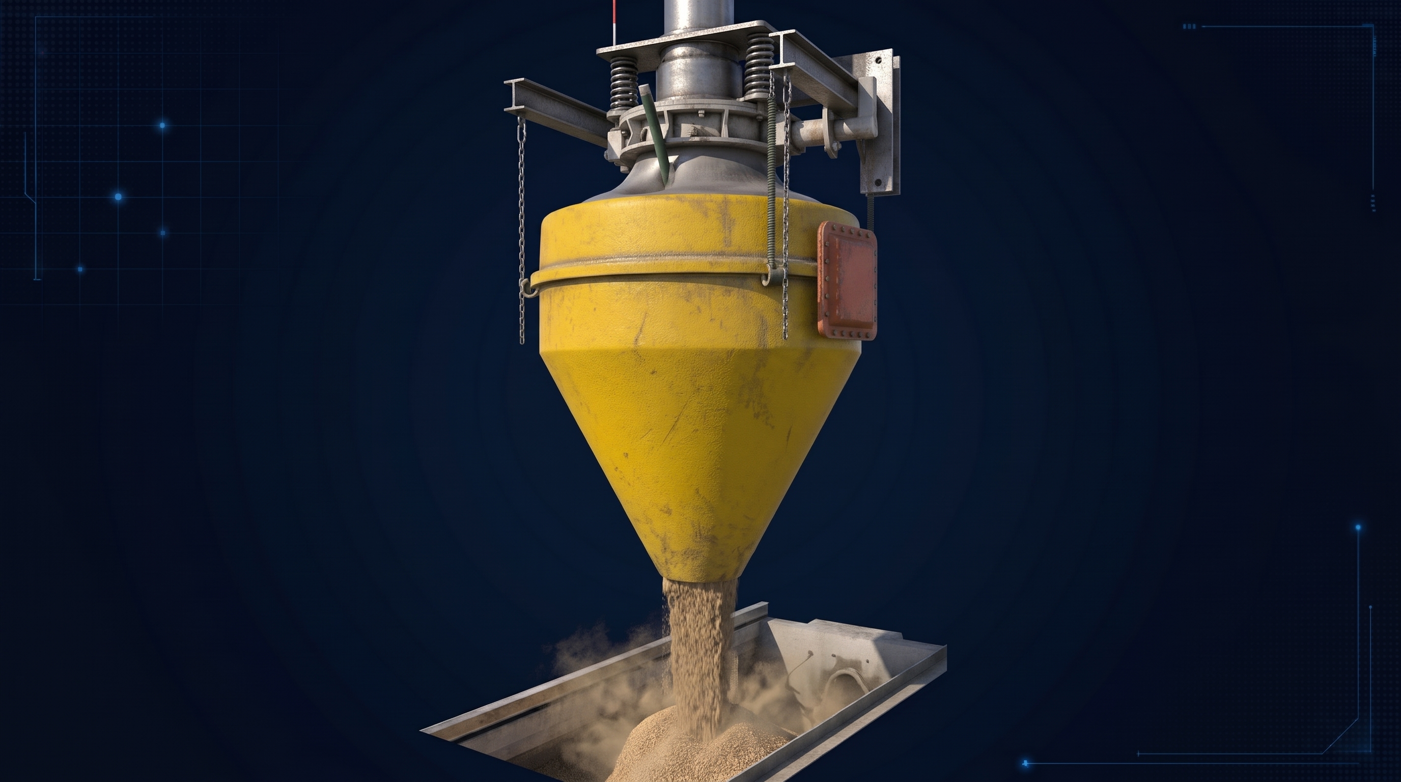
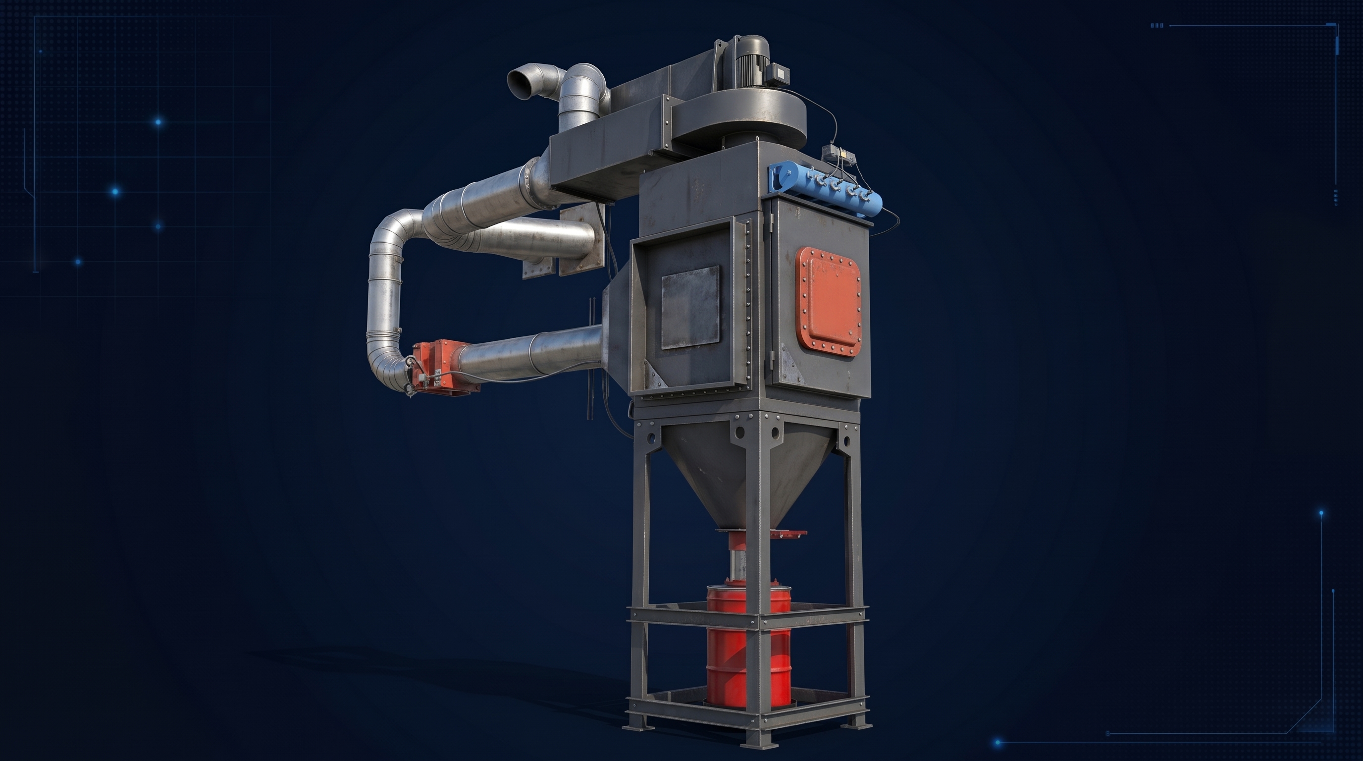
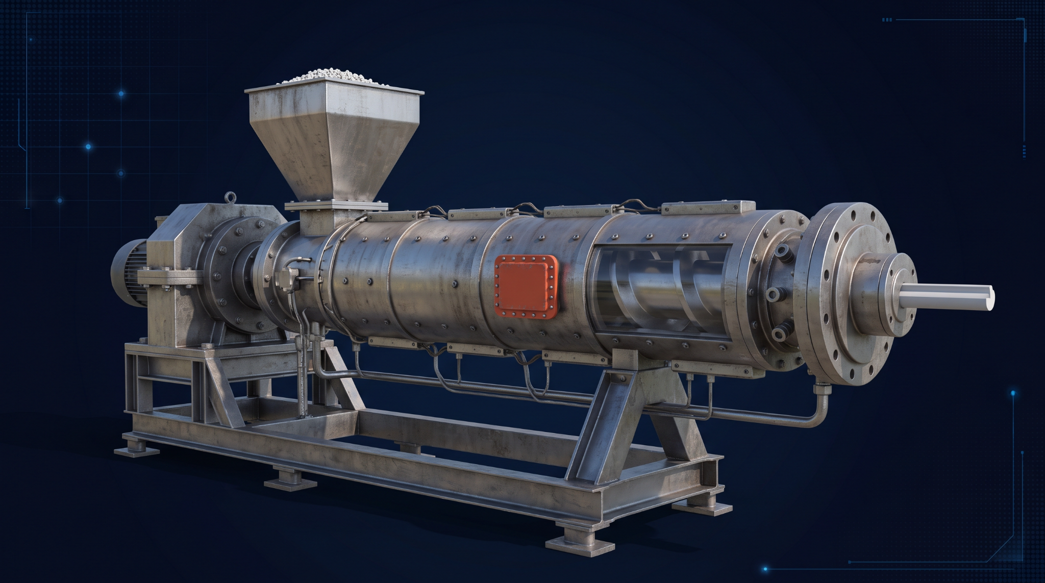
Enter verified values in the Dust Analysis inputs to enable calculations. If you do not know these values, use the Search GESTIS-DUST-EX button above to check the available data for your material. Confirm the suitability of the values for your application.
| Commercial Size | Nominal Area | Panels Required | Total Area Provided | Relief Coverage |
|---|
One-variable-at-a-time analysis using the currently selected sizing equation, coefficients, L/D correction and vessel inputs.
Static vent activation pressure · barg
Axes control display only. A custom X range also recalculates the curve within valid input bounds.
Reduced explosion pressure · barg
Axes control display only. A custom X range also recalculates the curve within valid input bounds.
Calculated fireball diameter (D) · metres
Whole-number panel counts from 1 to 16. Distance follows the active fireball equation.
| Manufacturer | Product / Series | Nominal Vent Size (mm) | Effective / Relief Area (cm²) | Action |
|---|
Use current manufacturer documentation for final engineering selection. Rows without a published effective/relief area remain visible but are not used to calculate panels required.
| Manufacturer | Product | Official Source | Notes | Action |
|---|
Manufacturer information is provided as a reference list. Verify current product specifications and availability with the manufacturer before engineering use.
Adjust each column width. All columns automatically share the available table width.
Widths are saved in this browser for your account. Long values may be shortened visually; select a field to read or edit its full value.
| No. | Dust Name | Median Particle Size (micro meter) | Kst (bar.m/s) | Pmax (barg) | K | Layer or cloud ignition temperature (°C) | Minimum Ignition Energy (mJ) | Reference | Action |
|---|
Units: Kst (bar·m/s), Pmax (barg), K (dimensionless), ignition temperature (°C). Missing values remain blank. Verify material test conditions before engineering use.
Analysis of your saved Dust Analysis calculations only
No saved calculations match these filters. Save a calculation or adjust the filters.
Charts reflect saved records for the signed-in account. Equipment counts use unique Equipment IDs; if an ID has multiple saved cases, its latest case is shown. Records without Plant or Equipment Type are categorized as Not recorded.
Click 'Load' to populate any saved record directly back into the live calculator
| Plant | Equipment Type | Equipment ID | Calculation Method | Kst (bar·m/s) | Pmax (barg) | No. of Panels | Area per Panel (m²) | Fireball DIA (m) | Dust Name | Load |
|---|
Click the button below or use "Save to My Account" in the calculator view to save and catalog equipment sizing runs.
Your rating contributes to the EcoSPRINT-DUST Tool cards across PSONE.
Community feedback about the EcoSPRINT-DUST Tool.
Sign in to get more features:
Already have an account? Sign in to unlock these tools.